Author name: David Wang

deliberate offset injections at the joint line
Lower Extremity

Deliberate Offset in Palpation-Guided Prolotherapy: Safe, Gradual Needle Progression (Part 1)

Deliberate Offset in Palpation-Guided Prolotherapy: Safe, Gradual Needle Progression (Part 1)

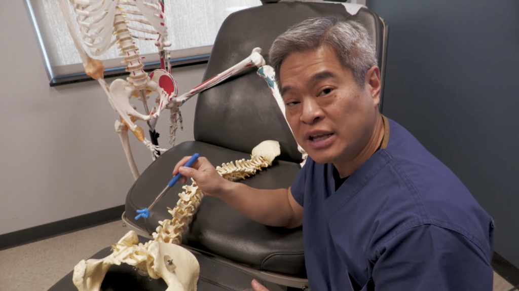
I’m Dr. David Wang from RPI, sharing a practical, clinician-focused approach to improving safety and accuracy in palpation-guided, non-image-guided prolotherapy injections. This is Part 1 of a two-part series designed to give you a robust framework you can apply in daily practice when navigating the shoulder’s upper joint without real-time imaging.

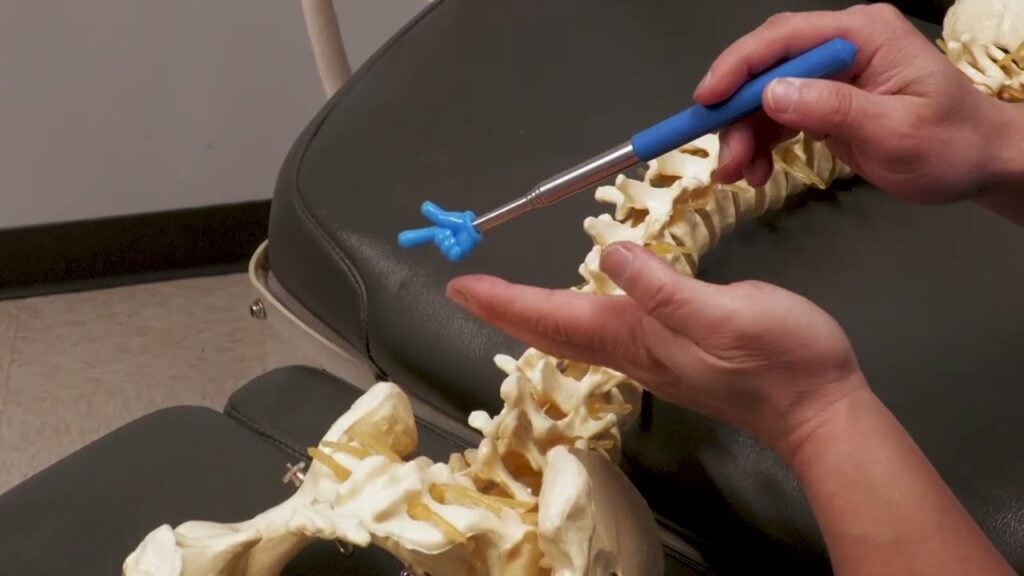
The central idea I want to convey is deliberate offset. This concept, borrowed from military training, helps you establish a reliable reference point when you don’t have an imaging modality guiding you. In injections around the shoulder, you often face a challenge: you’re unsure exactly where you are in relation to deep osseous landmarks and adjacent neurovascular structures. Deliberate offset asks you to take a controlled misdirection initially—move superficially or off-target by a small margin—so you can confirm your relative position against a known landmark before steering toward your actual target.

To illustrate, imagine your objective is the upper portion of the joint, with nearby neural structures as a cautionary reminder. You begin by entering at a very shallow angle, nearly parallel to the skin, deliberately avoiding bone on the first pass. This initial superficial pass tells you you’re safely above the surface and gives you a baseline for tissue depth. From there, you progressively increase the angle in small increments—five degrees at a time—while monitoring how much needle is exposed. A key cue is the needle’s depth: you’ll often notice the exposure decrease as you begin to approach the target plane, then suddenly plunge deeper once you cross a shallow-to-deep transition. That moment—the gummy sensation of the needle contacting deep tissue or bone—signals you’ve reached the correct osseous region for the prolotherapy injection.

This method has two powerful benefits. First, it provides a safer, more controlled path to a deep target, reducing the risk of accidentally traversing into neural foramina or misplacing the needle. Second, it offers a repeatable workflow across patients with different body habitus. By starting superficially and gradually offsetting deeper, you create a reliable, patient-specific trajectory that you can adjust in real time.

In the context of shoulder injections, the deliberate offset technique helps you localize the upper joint region with improved confidence. It’s particularly useful when landmarks are ambiguous or when you’re working near complex structures where precision matters for safety and efficacy. The technique is not a substitute for imaging guidance when it’s available, but it’s a valuable skill set for clinicians performing palpation-guided injections in regenerative medicine.

Click Here for Part 2

Deliberate Offset in Palpation-Guided Prolotherapy: Safe, Gradual Needle Progression (Part 1) Read Post »

deliberate offset prolotherapy
Lower Extremity

Advanced Deliberate Offset: Precision Palpation-Guided Injections at the Joint Line (Part 2)

Advanced Deliberate Offset: Precision Palpation-Guided Injections at the Joint Line (Part 2)

Continuing from Part 1, I’m Dr. David Wang of RPI, extending the deliberate offset technique with a more advanced application near the joint line. This installment demonstrates how to apply the same stepwise, controlled progression to another anatomical context—emphasizing safety and precision when working with small targets and nearby structures.

The premise remains the same: begin with a shallow entry to verify superficial anatomy, then incrementally deepen while maintaining a keen sense of needle depth and trajectory. In this example, the target is a small tibial structure just beneath the knee’s joint line. The medial joint line is a small, millimeter-scale target, often only a few millimeters long. Because the region houses several critical structures, accuracy is paramount, and image guidance is not always available in practice.

A crucial consideration is tissue thickness variability. The distance from skin to bone can range dramatically between patients, sometimes just a few millimeters and other times several centimeters. This variability makes it challenging to rely on a fixed depth or fixed degree-angle rule. Deliberate offset provides a flexible framework: you start superficially, progressively adjust depth and angle, and use tactile feedback—the “sonar” of the needle tip—to guide you to the target zone.

In this context, safety is the top priority. You’ll be navigating around structures such as the meniscus, cartilage, and fat pads. By offsetting initially and learning to feel when you’ve reached the correct layer, you minimize unnecessary needle passes and tissue trauma. The result is a safer, more efficient approach that can be adapted to various joints and targets beyond the shoulder.

If you’d like, I can format these posts for WordPress HTML blocks, add visuals, and provide a downloadable marking checklist to accompany the posts. And, as with Part 1, I’ll include an internal link back to Part 1 so readers can follow the full learning sequence.

Click Here for Part 1

Advanced Deliberate Offset: Precision Palpation-Guided Injections at the Joint Line (Part 2) Read Post »

Upper Extremity

Mastering AC Joint Landmarking for Shoulder Injections: Part 1 — Common Errors and Corrections

Mastering AC Joint Landmarking for Shoulder Injections: Part 1 — Common Errors and Corrections

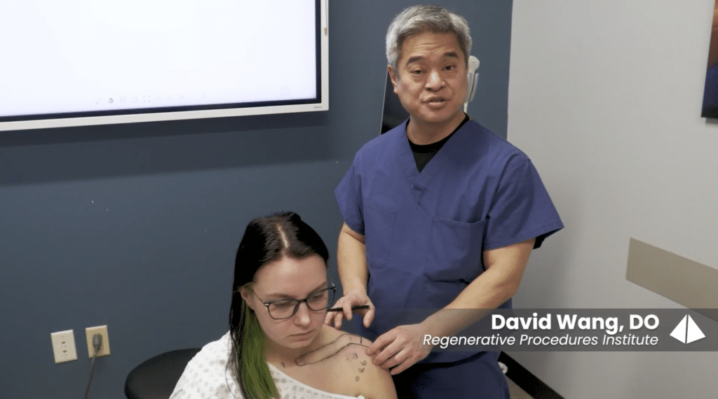
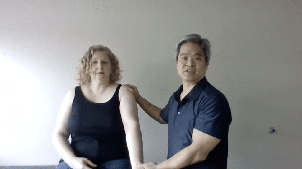
I’m Dr. David Wang from RPI, and I’m sharing a practical, clinician-focused guide to improve palpation-based landmarking for shoulder injections. This is Part 1 of a two-part series designed for orthopedic providers who want to translate palpable anatomy into accurate, safe injections around the clavicle and AC joint.

The shoulder region presents a challenging landscape for landmarks. The AC joint sits where the distal clavicle meets the acromion, but the superficial cues we rely on can be misleading. A frequent error I see is marking the sternoclavicular region or a lateral line in place of the true AC joint boundary. The sternoclavicular joint is near the sternal notch, a narrow landmark. When you place a line laterally across the shoulder to demarcate the AC joint, you risk overshooting medially or laterally, misaligning your subsequent injection plan. The sternal notch itself is relatively small, and it’s flanked by a clavicle that trails medially and laterally as it curves. Understanding this spatial relationship is essential for accurate injection targeting.

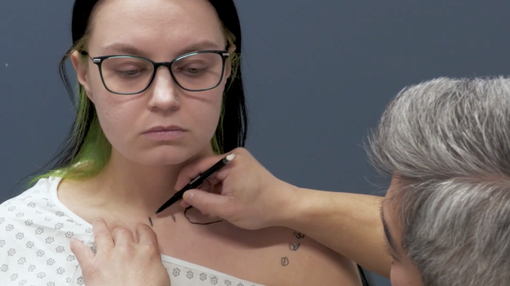
To avoid these missteps, I emphasize the concept of three divots around the AC area. The middle divot corresponds to the AC joint itself. The lateral divot marks the edge of the acromion, while the medial divot sits near the distal clavicle’s curvature. The challenge is that the distal clavicle is not a uniform edge; it has a subtle S-curve that transitions from a more cylindrical medial segment to a flatter distal segment. This curvature shifts the posterior border of the clavicle posteriorly, a detail that is easily masked by the trapezius muscle. If you rely on a straight-line approach to mark the clavicle, you’ll likely misplace the AC joint and, consequently, risk misdirecting your injection.

Another layer of complexity is distinguishing the coracoid process from the clavicle’s landmarks. The coracoid is a separate bony prominence, and confusing it with the medial clavicle can throw off your landmark map. Practically, I instruct residents and fellows to palpate with a purpose: identify the medial edge of the clavicle, then trace the clavicle’s S-curve toward the distal end, where it meets the V-shaped posterolateral corner. The V marks the termination of the clavicle and aligns with the AC joint line. This alignment is critical for planning injections near the superior labrum and adjacent structures.

With palpation alone, these landmarks can be elusive, particularly in patients with arthritic changes that alter bony margins. That’s why a robust mental map of distances helps: the midpoint of the AC joint is typically about two centimeters medial from the lateral edge of the acromion. This spatial rule of thumb provides a practical check when palpation feels uncertain. Even when the joint line isn’t easily palpable, knowing these relationships improves your odds of accurate injection localization.

In Part 2, we’ll move from landmark recognition to applying ultrasound guidance to refine our injections. We’ll describe a reproducible marking protocol that uses these landmarks, integrates with ultrasound visuals, and reduces tissue misplacement. If you’d like, I can tailor this content for a specific orthopedic subspecialty, or convert it into a workshop handout, diagram set, or printable marking checklist.

CLICK HERE FOR PART 2

Mastering AC Joint Landmarking for Shoulder Injections: Part 1 — Common Errors and Corrections Read Post »

Upper Extremity

Completing the Picture: Clavicle Landmarking, Curvature, and Safety for Shoulder Injections (Part 2)

Completing the Picture: Clavicle Landmarking, Curvature, and Safety for Shoulder Injections (Part 2)

I’m Dr. David Wang of RPI, continuing our focused discussion on accurate palpation-based marking for shoulder injections. This installment zooms in on the clavicle’s curvature, the posterior border, and the V landmark—crucial for accurate, safe injections near the clavicle and superior shoulder region.

The clavicle is not a uniform cylinder. The medial aspect remains relatively rounded, while the lateral portion flattens and widens, creating a dynamic landmark landscape. The posterior border of the distal clavicle sits further back than learners expect, largely due to the overlying trapezius and the clavicle’s curved anatomy. When marking, it’s essential to preserve the clavicle’s natural S-curve and to identify the V-shaped posterolateral clavicle corner, which marks the entry point for superior injections toward the labrum.

A critical error to avoid is misidentifying the coracoid process as part of the clavicle. The coracoid is a distinct structure, and misidentifying it can derail marking accuracy. By maintaining awareness of the clavicle’s curvature and its posterior border, you’ll be better equipped to target the superior shoulder region safely and effectively. To implement this in practice, mark the medial clavicle edge that truly reflects the medial boundary, outline the S-curve and posterior border, and identify the V landmark that guides injections toward the labrum region. When used with ultrasound guidance, this approach improves accuracy and reduces tissue misplacement.

CLICK HERE FOR PART 1

Completing the Picture: Clavicle Landmarking, Curvature, and Safety for Shoulder Injections (Part 2) Read Post »

Spine, Nerves

Thoracolumbar Fascia at the PSIS: Ultrasound Diagnosis and Injection Guide

Thoracolumbar Fascia at the PSIS: Ultrasound Diagnosis and Injection Guide

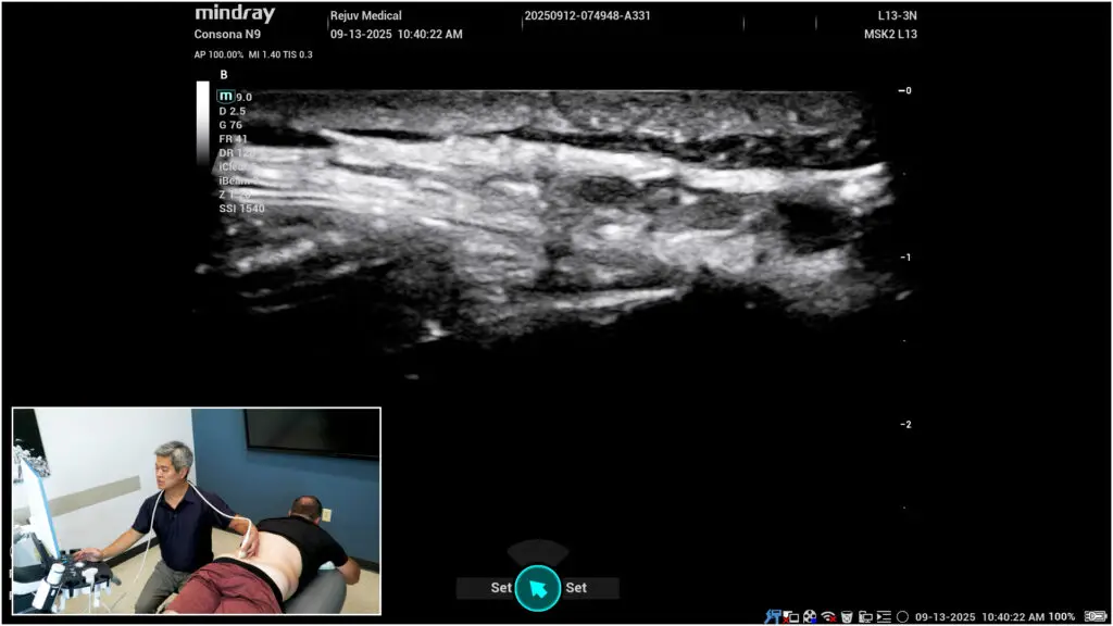
Axial low back pain that patients localize with a fingertip over one or both posterior superior iliac spines (PSIS) often implicates the thoracolumbar fascia (TLF). With ultrasound, you can reliably identify the PSIS, visualize both deep and superficial TLF bands, and target regenerative injections to the most pathologic tissue.

Clinical pattern

When asked, many patients point to “that spot” just over the PSIS on one or both sides. This aligns with the primary TLF attachment on the posterior-superior aspect of the ilium. Reproducible point tenderness here—especially with resisted trunk motions or prolonged standing—raises suspicion for TLF strain/degeneration.

Find the PSIS fast

If surface anatomy is challenging (e.g., higher BMI), use the thenar eminence as a broad palpation tool to locate the bony prominence. Set your fingertips where the thenar eminence lands to fine-tune position.

Ultrasound roadmap

1) Orient in transverse (short axis) to confirm PSIS.

  • On screen, set medial = right and lateral = left (match your machine conventions).
  • Identify the superficial PSIS cortex.

2) Deep band (long axis over the PSIS ridge).

  • Pivot to long axis so the PSIS cortex spans the screen.
  • Scan medially↔laterally to survey the deep TLF attachment.
  • Pathology clues: cortical irregularity, hypoechoic change at the enthesis, or loss of crisp fibrillar interfaces consistent with chronic strain/degeneration.
  • Injection: in-plane or out-of-plane tracking along the ridge where the deep band anchors.

3) Superficial band (rotate 60–90°).

  • Pivot the superficial end medially until a bright, thick, superficial band comes into view descending to the PSIS.
  • Pathology is often more frequent here: look for hypoechoic banding, focal calcific/enthesophyte change, or disrupted echotexture.
  • Sweep to capture the worst segment—many patients show maximal findings slightly lateral to midline.

Injection technique pearls

  • Target the most abnormal segment (superficial more often symptomatic); treat the deep band when cortical irregularity/hypoechogenicity is prominent at the ridge.
  • Keep the needle in-plane when feasible for precise deposition; use small test volumes to confirm plane/spread.
  • Hydrodissect along the diseased layer to restore glide, then deliver your chosen regenerative solution (e.g., dextrose, PRP) into the fascial plane/enthesis.
  • Avoid intratendinous spread into adjacent gluteal or paraspinal tendons unless intentionally treating them.
  • Combine with a load-management plan (hip hinge mechanics, posterior chain strength, lumbopelvic stabilization) to reduce recurrence.

Why this matters

The PSIS-level TLF is a high-yield pain generator in axial LBP and often overlooked when imaging focuses only on discs or facet joints. Systematic ultrasound evaluation of deep vs superficial bands lets you localize pathology and treat precisely, often producing meaningful relief in patients who’ve “tried everything.”

Thoracolumbar Fascia at the PSIS: Ultrasound Diagnosis and Injection Guide Read Post »

Spine, Clinic Operations, Lower Extremity, Nerves, Upper Extremity

Ultrasound-Guided Needling: A Stepwise Technique You Can Trust

Ultrasound-Guided Needling: A Stepwise Technique You Can Trust

Ultrasound guidance can take injections from “good enough” to precise, safe, and reproducible—especially near small targets like nerves. This quick guide distills a stepwise approach you can apply immediately in clinic.

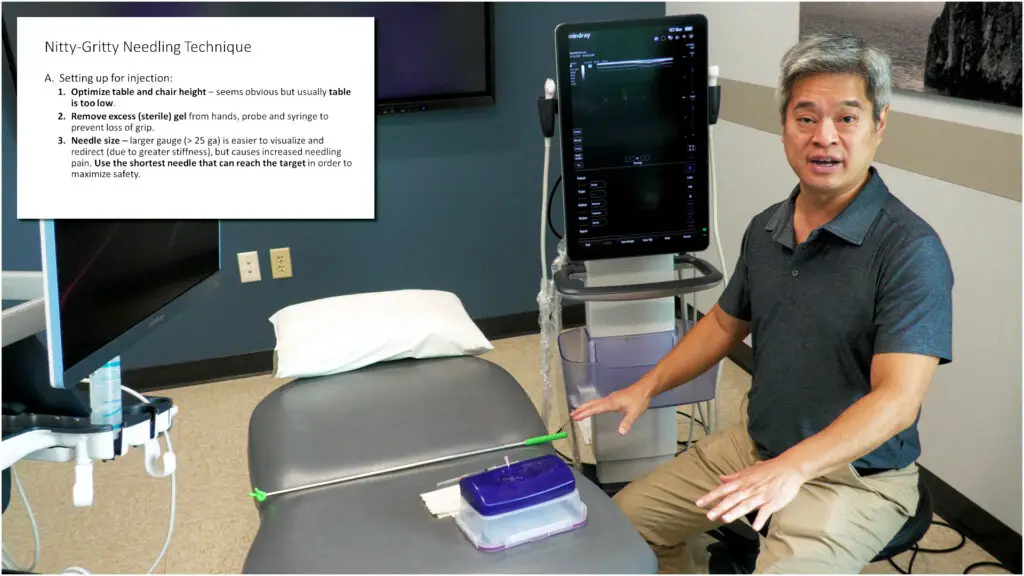
1) Set up before you scan

  • Ergonomics first: Adjust table/chair height so a shallow in-plane angle feels natural. If the table is too low, you’ll default to a steep, hard-to-control trajectory.
  • De-gel for control: Diagnostic scans love extra gel; injections do not. Wipe probe, hands, and syringe so you can make micro-movements without slipping.
  • Right tools: Prefer the shortest needle that reaches the target. Use smaller gauges (e.g., 25G) for patient comfort as your skill grows. Match syringe size to control—smaller barrels are easier to finesse; learn alternate grips for stability and continuous injection.

2) Master the probe hold (micro-moves matter)

Use a three-finger wrap high on the probe with the 4th/5th fingers resting on the patient. This balances stability with mobility, enabling all five motion families (slide long/short axis, rotate, tilt, heel-toe) in tiny increments. Flex the wrist—this “intentional discomfort” increases leverage and fine control.

3) Line up like a pool cue

Before inserting the needle, align patient → target → probe → injecting hand → eyes → screen. Keep the second monitor low enough that you glance with your eyes, not your neck. Minimize skin-to-target distance: position the probe so your path is short and your needle can stay shallow.

4) Geometry beats guesswork

  • Depth decides angle. Estimate target depth and pick an initial angle (e.g., ~30–45°) relative to the probe, not the room. If you tilt the probe (to fight anisotropy), adjust needle angle to match.
  • Stand off the footprint. Avoid inserting right against the probe—maintain room to pivot and protect the transducer.

5) Keep the needle in view (and prove it’s the tip)

Three visualization boosters:

  1. Heel-toe toward the needle to make the beam more perpendicular—needle brightens dramatically.
  2. Oscillate the needle (tiny in-out “sewing” motion) while keeping net depth unchanged.
  3. Lateral sweep the probe ~5 mm each way—like radar—to pass over the true tip.
    Safety check: the on-screen motion of the tip must match your hand movement; if not, you’re probably seeing shaft, not tip.

6) Correct deliberately—don’t “fish”

If you’re off target, retract almost to skin, adjust angle, then re-advance. Don’t bend the needle by steering while deep. Frequently look at your hands to ensure the probe is centered over the needle path (dominant-hand drift is common). Break contact points if needed—another moment of intentional discomfort that prevents hidden angle changes.

7) Progress thoughtfully

Skill progression runs: safe → effective → minimal pain → efficient → effortless. Smaller needles, fewer redirects, and consistent visualization take thousands of iterations—but they spare patients bruising and you frustration.

Ultrasound-Guided Needling: A Stepwise Technique You Can Trust Read Post »

Lower Extremity

Medial & Lateral Patellar Retinacula: Quick Anatomy, Ultrasound Landmarks, and Clinical Clues

Medial & Lateral Patellar Retinacula: Quick Anatomy, Ultrasound Landmarks, and Clinical Clues

Anterior knee pain isn’t always patellar tendon or fat pad. The patellar retinacula—medial and lateral fibrous expansions paralleling the patellar tendon—are frequent, under-recognized generators. Distinguishing them clinically and with ultrasound helps you target treatment and avoid misdiagnosis.

Anatomy at a Glance

  • Fiber direction: The retinacula run mainly longitudinally, flanking the patellar tendon.
  • Contrast with MPFL/LPFL: Medial and lateral patellofemoral ligaments trend more transversely, stabilizing the patella against lateral/medial translation.
  • Distal relationships:
    • Lateral retinaculum blends with distal IT band and tracks toward the Gerdy’s tubercle region.
    • Medial retinaculum anchors toward the medial anterior tibia near the tibial tubercle/medial tibial flare.

Ultrasound Roadmap

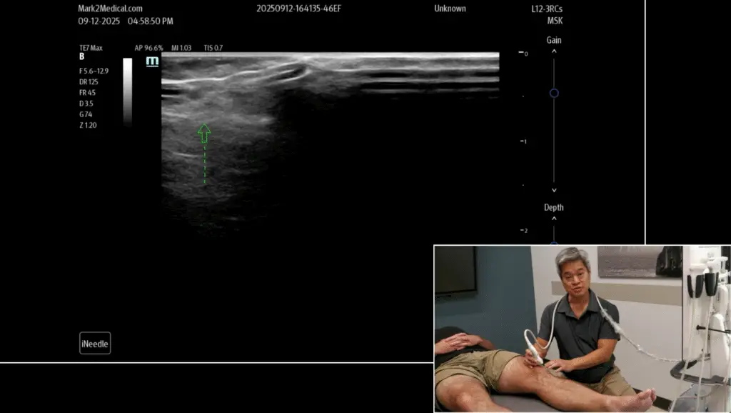
Start in longitudinal view on the patellar tendon (inferior pole of patella to tibial tuberosity). In this orientation: proximal/superior → right; distal/inferior → left.

Lateral Sweep

  1. Anchor: Identify the patellar tendon over the tibial tuberosity.
  2. Slide laterally: The tendon and tuberosity fade; a wispy, hyperechoic, linear band appears—this is the lateral retinaculum.
  3. Keep going laterally: You’ll encounter the IT band, a thicker echogenic structure inserting at Gerdy’s tubercle.
  4. Pathology hints: Cortical irregularity at the tibial cortex and focal hypoechoic change within the retinaculum suggest strain or enthesopathy.

Medial Sweep

  1. Cross midline: From patellar tendon, slide medially until the tendon disappears.
  2. Identify the band: The medial retinaculum again looks wispy and hyperechoic, coursing longitudinally.
  3. Landmarks: It tracks toward the medial anterior tibia beside the tibial tubercle. Continue medially to visualize MCL and medial meniscus.
  4. Pathology hints: Look for cortical irregularity and focal hypoechogenicity at the tibial attachment or within the band.

Clinical Pattern Recognition

  • Symptoms: Patients report focal, infrapatellar medial or lateral pain that’s point-tender directly over the distal retinacular attachments (medial anterior tibia for the medial retinaculum; Gerdy’s region for the lateral).
  • Provocation: Squatting, stairs, or prolonged sitting may irritate, but direct palpation reproduces their exact pain.
  • Differentiate from look-alikes:
    • Patellar tendinopathy: Max tenderness is midline along the patellar tendon/tuberosity, not off to the medial/lateral tibial flare.
    • Fat pad impingement: Pain is more infrapatellar midline with fullness and pinch signs; ultrasound shows hypoechoic Hoffa’s fat pad changes.
    • PF maltracking (MPFL/LPFL): Pain often more peripatellar with history of instability; ligaments run transverse and localize differently on imaging.

Treatment Considerations

  • Targeted load management: Modify squat depth, step-downs, and lateral movements that tension the involved side.
  • Manual/IASTM & mobility: Address lateral/medial soft-tissue stiffness (IT band/TFL laterally; medial retinacular tightness medially).
  • Strength & control: Emphasize quads (especially VMO bias), hip abductors/external rotators, and patellar tracking drills.
  • Image-guided care: For persistent focal tenderness with corroborating ultrasound findings, consider periretinacular hydrodissection or needling; reserve injections for recalcitrant cases after rehab optimization.

Bottom Line

If the pain sits just off midline and palpation over the medial/lateral tibial flare exactly reproduces it, think retinacular. Use ultrasound’s “wispy band” sign plus cortical cues to confirm—and treat the right tissue.

Medial & Lateral Patellar Retinacula: Quick Anatomy, Ultrasound Landmarks, and Clinical Clues Read Post »

knee physical exam orthopedics
Lower Extremity, Nerves

The Hip Physical Exam: A Tissue-Type Mindset for Precise Diagnosis

The Hip Physical Exam: A Tissue-Type Mindset for Precise Diagnosis

A great hip exam starts before you touch the patient—with your mindset. Approaching complaints by tissue type (skin, subcutis, fascia, muscle, tendon, ligament, bursa/capsule) versus orthopedic structures (bone, joint, cartilage, labrum, nerves) helps you form a tighter differential, choose the right procedures (e.g., peritendinous vs intra-articular), and even anticipate accurate documentation and codes.

History Heuristics: Compression vs Stretch

  • Joint/bone pain tends to worsen with compressive or provocative intra-articular motions (e.g., flexion, internal rotation). Patients with hip OA often hurt with axial loading or “grinding” positions.
  • Soft-tissue pain (ligament/tendon) typically worsens with stretch (e.g., passive abduction aggravating adductor pathology).
  • Nerve pain reproduces with tension tests (distribution-consistent radicular symptoms).

Range of Motion & Nerve Tension

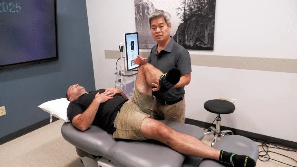
  • ROM: Flexion ≈120°; ER ≈40–60°; IR ≈30–40°. Early loss of internal rotation plus deep anterior/groin pain suggests intra-articular pathology.
  • Nerve tests:
    • SLR positive ~30°–70° for L5/S1 radicular pain; augment with ankle dorsiflexion (e.g., Bragard/Lasegue variants).
    • Femoral stretch test (prone) for higher roots.

Intra-Articular Screens

  • Scour test (quadrant): Axial load through the femur while sweeping arcs; anterior-superior quadrant is commonly symptomatic in labral disease. Sensitive but not perfectly specific—correlate with exam.
  • FABER (Flexion–Abduction–External Rotation): Reproduces anterior hip or posterior buttock pain depending on pain source; add gentle overpressure with contralateral ASIS stabilization.
  • Log roll: Passive internal/external rotation with the patient supine; highly specific in practice for intra-articular pathology when clearly positive.

Active Strength to Isolate Structures

Functional anatomy sharpens localization:

  • Hip flexors:
    • Knee extended (tests iliopsoas + rectus femoris).
    • Knee flexed (biases iliopsoas, reduces rectus contribution).
      Pain only with knee extended → suspect rectus femoris; pain with both → consider iliopsoas.
  • Quadriceps vs rectus femoris:
    • Straight-leg hip flexion activates all quads including rectus.
    • Supported thigh with knee extension only emphasizes vasti over rectus.

Surface Palpation: Landmarks That Matter

Palpation is highly sensitive—if you know what you’re pressing on.

  • ASIS: Proximal sartorius/inguinal ligament; use the thenar eminence first to find bony prominences in higher BMI patients, then fine-tune with fingertips.
  • AIIS: Proximal rectus femoris—often exquisitely tender; be gentle.
  • Greater trochanter: Lateral pain is frequently gluteus medius/minimus tendinopathy; TFL/IT band lies more anterior and blends distally to Gerdy’s tubercle.
  • Iliac crest (posterior-superior rim): Proximal gluteal tendon attachments can be tender.
  • Ischial tuberosity (sits bone): Most tenderness is posterior-superior (proximal hamstrings, sacrotuberous ligament).
    • History pearl: Hard surface sitting pain → hamstring/sacrotuberous bias. Soft surface sitting pain → think obturator internus (tension across the posterior ischium).
  • Correlate palpation with diagnostic ultrasound to verify tissue injury and guide targeted injections/hydrodissection.

Clinical Takeaway

Think tissue first, then confirm with targeted maneuvers: compression for joints, stretch for soft tissues, tension for nerves. Combine ROM, scour/FABER/log roll, strength isolation, and precise palpation to localize the pain generator—and treat the right structure the first time.


The Hip Physical Exam: A Tissue-Type Mindset for Precise Diagnosis Read Post »

Lower Extremity

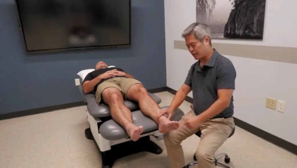
Foot & Ankle Physical Exam: A Fast, Structured Walkthrough

Foot & Ankle Physical Exam: A Fast, Structured Walkthrough

Dr. Wang lays out a practical, clinician-friendly foot and ankle exam using the classic flow: inspection → palpation → range of motion → special tests. Here’s the distilled playbook.

1) Inspection (standing and supine)

Standing (360° look):

  • Alignment & deformity: toe rotation, valgus/varus, hallux valgus, claw/hammer/mallet toes.
  • Arch/biomechanics: compare arches side to side. Use a quick “finger under the arch” screen; relative pes planus is often obvious visually.
  • “Too many toes” sign: from behind, seeing more lateral toes on one side suggests posterior tibialis dysfunction and medial arch collapse.
  • Heel rise test: during plantarflexion, a subtle lateral shift of the ankle/medial heel at end-range is normal; loss of this excursion suggests hindfoot/ subtalar instability.
  • Tendons/bursae: look for fusiform thickening of the Achilles and swelling in the retrocalcaneal bursa.

Supine:

  • Survey for edema (check pitting), erythema, ecchymosis (often migrates distally over days), and focal swelling over joints/tendons.

2) Palpation (think quadrants)

Patients often localize pain precisely—use that advantage.

Anterior:

  • Joint line (tibiotalar) vs extensor tendons (TA, EDL, EHL).
  • Tarsometatarsal (TMT/Lisfranc) region: anatomy is dense; identify the tender point, then correlate with imaging or ultrasound to map talus → navicular → cuneiforms → metatarsals.

Medial:

  • Deltoid ligament (proximal to malleolus) and sustentaculum tali (just inferior)—common tender spots.
  • Behind the medial malleolus (Tom, Dick, AN, Tom): TP (most commonly symptomatic), FDL, artery/veins/nerve, FHL. Trap TP against bone to provoke focal tenderness.
  • Spring ligament and navicular plantar-medial tenderness; plantar fascia origin just anteromedial to the calcaneal tuberosity.

Lateral:

  • ATFL (from lateral malleolus toward big toe)—hallmark tenderness after inversion sprain.
  • Sinus tarsi (anterior–inferior “divot”): deep ligament pain in repetitive inversion injuries (sinus tarsi syndrome).
  • Peroneals behind the malleolus; look for retinacular pain, popping/subluxation, and fibularis brevis insertion pain at the base of the 5th metatarsal (differentiate stress/“marcher’s” fracture vs Jones avulsion).

Posterior/Plantar:

  • Achilles: watershed zone 2–6 cm proximal to insertion is classic for tendinopathy; fusiform swelling is typical.
  • Plantar fascia (medial > lateral band), plantar plate tenderness (apply distal-to-proximal directed pressure), sesamoids (medial/lateral).

3) Range of Motion (ROM)

  • Dorsiflexion/Plantarflexion: posterior chain tightness vs anterior impingement; dancers may report posterior impingement in PF.
  • Inversion/Eversion: inversion stresses ATFL/CFL; eversion is less common but can be painful with deltoid injury.
  • Midfoot/forefoot torsion: assess pronation–supination mechanics.
  • Hallux MTP: screen for hallux rigidus/limitus (loss of extension most common).

4) Special Tests

  • Thompson test: prone calf squeeze → absent PF = Achilles rupture.
  • Anterior drawer: calcaneus forward on stabilized tibia → ATFL laxity.
  • Talar tilt (inversion stress): targets CFL.
  • External rotation stress test: stabilizes tibia, externally rotates foot → distal pain (and sometimes proximal fibular symptoms) suggests syndesmotic (“high ankle”) sprain.
  • Metatarsal torsion test: invert/evert forefoot while stabilizing midfoot—reproduces pain/laxity at TMT joints.
  • Intermetatarsal shear: isolate motion between adjacent metatarsals to detect intermetatarsal ligament sprain.
  • Metatarsal squeeze (Morton’s neuroma): ML compression of distal metatarsals with head stabilization → neuropathic pain/paresthesia.
  • Grind tests (axial load + circumduction): sensitive for MTP/IP arthropathy—start gently.

Pearls

  • Let patient-pointed tenderness guide you; the foot’s localization is often exact.
  • Map pain by quadrant, then confirm with ultrasound or plain films for joint/tendon differentiation.
  • Don’t miss posterior tibialis dysfunction, sinus tarsi syndrome, Achilles watershed tendinopathy, 5th metatarsal base fractures, and syndesmotic injury—they change management.

Foot & Ankle Physical Exam: A Fast, Structured Walkthrough Read Post »

Scroll to Top